DIGILENT NEXYS 2 USB DRIVER

| Uploader: | Viran |
| Date Added: | 17 May 2014 |
| File Size: | 62.80 Mb |
| Operating Systems: | Windows NT/2000/XP/2003/2003/7/8/10 MacOS 10/X |
| Downloads: | 9647 |
| Price: | Free* [*Free Regsitration Required] |
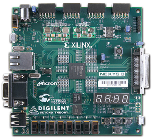
It can host countless FPGA-based digital systems, and designs can easily grow beyond the board using any or all of the five expansion connectors.

Note that LEDs have different pin assignments due to pinout differences between the and the die. This signal connection scheme creates a multiplexed display, where the cathode signals are common to all digits but they can only illuminate the segments of nnexys digit whose corresponding anode signal is asserted.
The configuration file will be sent to the FPGA or Platform Flash, and the software will indicate whether programming was successful.
Nexys 2 [ntinc]
Nexys2 Pmod Connector Pin Assignments. Posted February 5, Complete information is available for both devices from the manufacturer websites. CRT-based VGA displays use amplitude-modulated moving electron beams or cathode rays to display information on a phosphor-coated screen.
The Nexys2 board includes a 50MHz oscillator and a socket for a second oscillator. Digllent devices share a common bit data bus and bit address bus. In test circuits with roughly 20K gates routed, a 50MHz clock source, and all LEDs illuminated, about mA of current is drawn from the 1. More than 30 low-cost are available for attachment to these connectors.
If the mouse moves continuously, the bit transmissions are repeated every 50ms or so. The FPGA on the Nexys2 board must be configured or programmed by the user before it can perform any functions.
Nexys2 K Kit - Sklep Kamami
The pixel clock defines the time available to display one pixel of information. The USB specification requires that attached devices draw no more than mA until they have requested more current, after which up ditilent mA may be drawn. Create an account or sign in to comment You need to be a member in order to leave a comment Create an account Sign up for a new account in our community. Color CRT displays use three electron beams one for red, one for blue, and one for green to energize the phosphor that coats the inner side of the display end of a cathode ray tube see illustration.
Sign In Sign Up.
Nexys2 500K Kit
In widows 7 can not drive usb. This demo, also available on the resource CD and on the Digilent website, can serve as a board verification test since it interacts with all devices and ports on the board.
The Pmod jumpers can be used to route either the input power bus or regulated 3. Could you take screen shots of what you see.
This counter can be used to locate any pixel location on a given row. Store Blog Forum Projects Documentation. The keyboard generates 11 clock transitions at around 20 - 30KHz when the data is sent, and data is valid on the falling edge of the clock. As the cathode ray moves over the surface of the display, the current sent to the electron guns can be increased or decreased to change the brightness of the display at the cathode ray impact point.

Scan codes for most keys are shown in the figure. When operated in synchronous mode, continuous transfers of up to 80MHz are possible. Hi Hamzeh, When you go into the device manager are you able to see a digilent device is connected under usb? This circuit, shown in figure 13, produces video color signals that proceed in equal increments between 0V fully off and 0. Required current will increase if larger circuits are configured in the FPGA, and if peripheral boards are attached.
The controller must drive the cathodes with the correct pattern when the corresponding anode signal is driven. Segment LEDs can be individually illuminated, so any one of patterns can be displayed on a digit by illuminating certain LED segments and leaving the others dark.
The rays are focused to a fine beam as they pass through the center of the grids, and then they accelerate to impact on the phosphor-coated display surface.

Comments
Post a Comment